| Model | DXB-3 | DXB-4 | DXB-5 | DXB-6 | DXB-7 | DXB-8 | DXB-9 | DXB-10 | DXB-11 | DXB-12 | DXB-13 | DXB-14 | DXB-15 |
| Cooling Capacity* (KW) | 12 | 18 | 25 | 35 | 50 | 65 | 80 | 100 | 120 | 140 | 170 | 220 | 260 |
| Rated Flow (L/min) | 100 | 150 | 200 | 250 | 300 | 350 | 400 | 500 | 600 | 700 | 800 | 900 | 1000 |
| Working Pressure (bar) | 20 | 20 | 20 | 20 | 20 | 20 | 20 | 20 | 20 | 20 | 20 | 20 | 20 |
| Fan Power (KW) | 0.55 | 0.75 | 1.1 | 1.5 | 1.5 | 2.2 | 3 | 3 | 4 | 2*2.2 | 2*3 | 2*3 | 2*4 |
| Inlet&Outlet Thread | G1" | G1¼" | G1¼" | G1¼" | G1¼" | G1¼" | G1½" | G1½" | G1½" | G2" | G2" | G2" | G2" |
| Thermometric Thread | G3/8" | G3/8" | G3/8" | G3/8" | G3/8" | G3/8" | G3/8" | G3/8" | G3/8" | G3/8" | G3/8" | G3/8" | G3/8" |
| Noise Level** (dB) | 62 | 66 | 68 | 75 | 77 | 80 | 83 | 87 | 92 | 85 | 86 | 92 | 98 |
| A (mm±2) | 427 | 532 | 587 | 632 | 632 | 752 | 837 | 972 | 1082 | 1442 | 1642 | 1842 | 2047 |
| B (mm±2) | 503 | 563 | 603 | 623 | 623 | 763 | 919 | 1059 | 1208 | 763 | 913 | 1043 | 1193 |
| C (mm±2) | 350 | 350 | 350 | 450 | 450 | 450 | 500 | 600 | 600 | 450 | 500 | 600 | 600 |
| D (mm±2) | 290 | 390 | 450 | 490 | 490 | 560 | 645 | 700 | 700 | 560 | 645 | 700 | 800 |
| E (mm±2) | 310 | 310 | 310 | 400 | 400 | 400 | 450 | 550 | 550 | 400 | 450 | 550 | 550 |
| F (mm±5) | 384 | 434 | 475 | 495 | 495 | 634 | 780 | 920 | 1070 | 600 | 760 | 900 | 1050 |
| G (mm±5) | 50 | 55 | 55 | 55 | 55 | 55 | 60 | 60 | 60 | 75 | 70 | 65 | 65 |
| K (mm±10) | 496 | 530 | 535 | 611 | 631 | 656 | 686 | 686 | 713 | 706 | 706 | 706 | 713 |
| L (mm±2) | 40 | 40 | 40 | 45 | 45 | 45 | 55 | 55 | 55 | 45 | 55 | 55 | 55 |
| M (mm±2) | 12*18 | 12*18 | 12*18 | 12*18 | 12*18 | 14*22 | 14*22 | 18*25 | 18*25 | 14*22 | 14*22 | 18*25 | 18*25 |
| W1 | 180 | 200 | 220 | 250 | 280 | 320 | 380 | 400 | 500 | 320 | 380 | 400 | 500 |
| W2 | 380 | 400 | 450 | 500 | 550 | 650 | 750 | 800 | 1000 | 650 | 750 | 800 | 1000 |
| Note: * Cooling capacity: cooling power at △T=40℃. ** The noise value is measured at a distance of 1m from the cooler, which is only for reference. Because it is affected by the surrounding environment, medium viscosity and reflection. *** This table only takes AC380V-50HZ as an example. **** Energy efficiency index:YE2; Motor protection level: IP55; Insulation class: F. (Other options please contact DONGXU) | |||||||||||||
 Don't corrode aluminum alloys: ① Hydraulic oil ② lubricating oil ③ Water and water-soluble liquids... Water and Glycol Mixtures, please consult us.
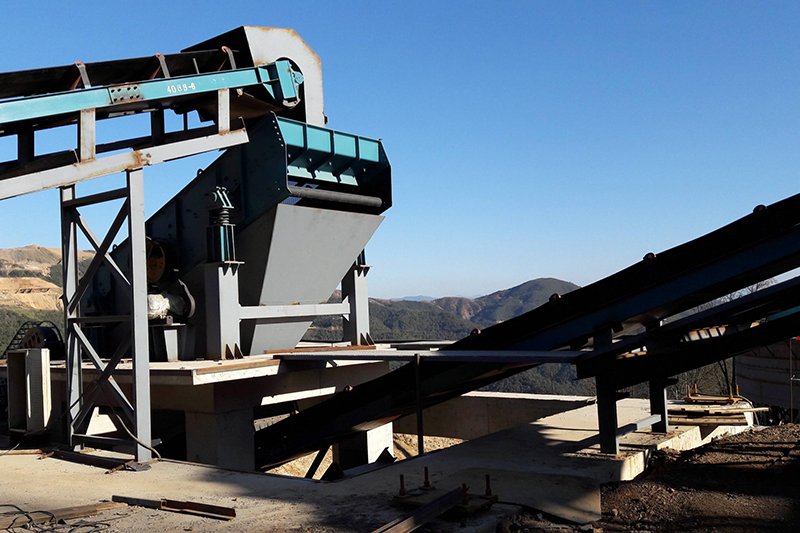
Construction machinery
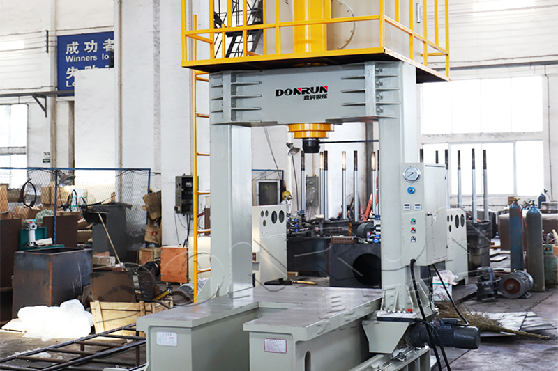
Hydraulic Machinery
Power Station
| DXB | 8 | A3 | 5 | N | C | X | O | O |
| Cooler Type: Efficient Motor Drive Series | Plate Size: 3/4/5/6/7/8/9/10/11/12/13/14/15 | Voltage: A3=AC380V⬅Standard A4=AC440V A5=AC660V | Frequency: 5=50Hz⬅Standard 6=60Hz | Bypass Valve: N=Build-in⬅Standard W=External M=Without Bypass Valve | Oil Hole Direction: C=Side in side out⬅Standard S=Up in up out | Wind Direction: X=Suction⬅Standard C=Blowing | Temp. Controller: O=Without controller⬅Standard T=Temp. Switches--Action Temp.: T50=50℃,T60=60℃,T70=70℃ C=Temp. Transmitter-- C1=Compact,C2=Digital | Heatsink Protection: O=Without protection⬅Standard S=Anti-Stone net |
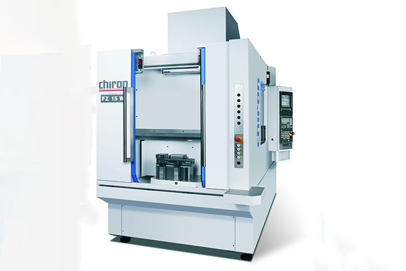
Machine tools
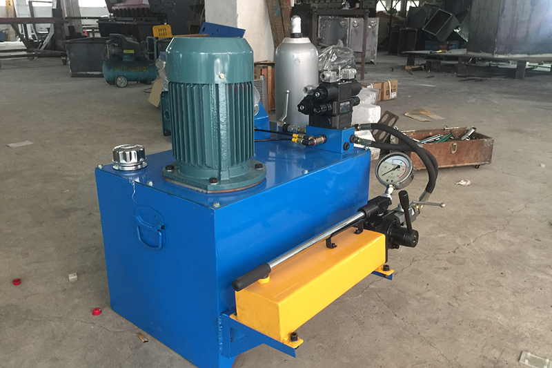
Hydraulic system circuit, independent cooling circuit and lubricating oil cooling system. For examples, machine tools, mining machinery, hydraulic machinery, power station, wind power equipment, and so on.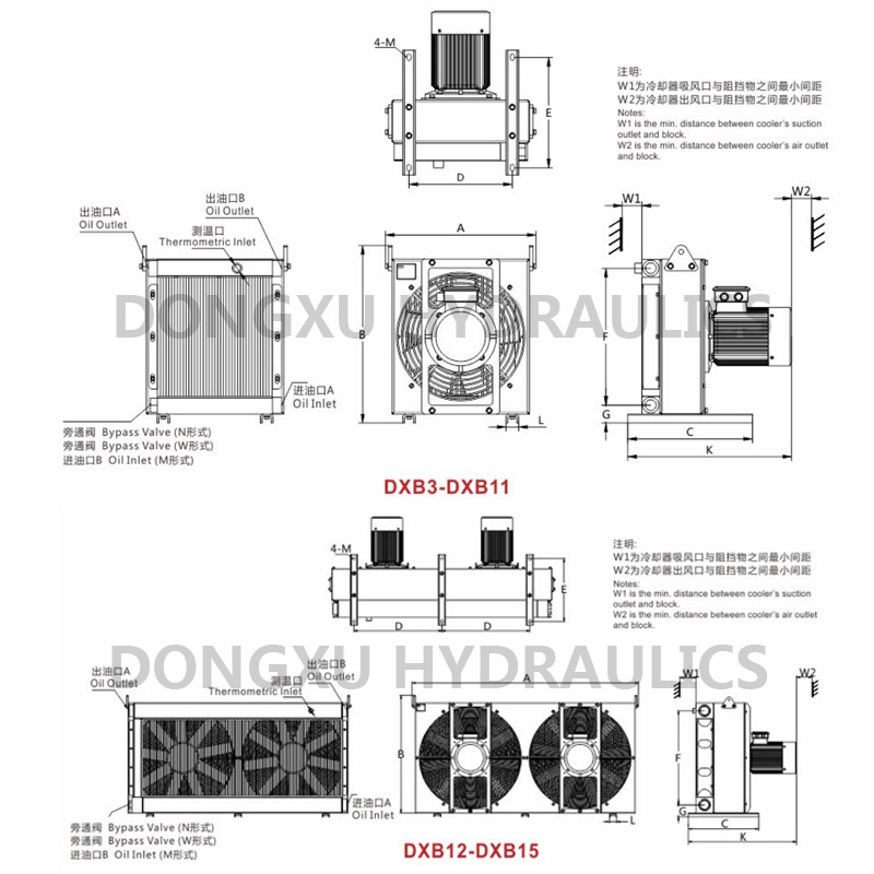
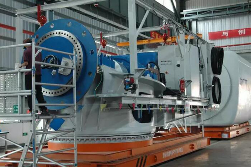
Wind Power Equipment
Dongxu air coolers are equipped with various forms of bypass circuits to protect the cooler core from damage. A. Pressure Bypass Circuit The pressure bypass circuit is divided into built-in and external pressure bypass circuits, and the opening pressure of the bypass valve is set to 5bar. When the fluid pressure inside the cooler is less than or equal to 5bar, the bypass valve is closed, and the fluid circulates back to the tank through the cooler's internal passage. When the pressure of the fluid entering the cooler is greater than or equal to 5 bar, the bypass valve is opened, and the fluid does not pass through the internal passage of the cooler, but returns directly to the fuel tank through the bypass circuit. In this way, the damage to the cooler caused by the back pressure formed by the shock pressure and the excess flow is avoided or reduced. B. Temperature Control Bypass Circuit The operating temperature of the temperature control bypass circuit temperature control valve is 40C°, that is: - When the oil temperature is ≤40C°, the temperature control valve is opened, the oil does not pass through the cooler, and the bypass circuit returns directly to the oil tank. This avoids damage to the components of the cooler system due to excessive back pressure at low temperatures. - When the oil temperature is >40C°, the opening of the temperature control valve gradually becomes smaller. At this time, part of the fluid passes through the cooler, and part of the fluid returns directly to the oil tank. - When the oil temperature is greater than 60C°, the temperature control valve is completely closed, and all the fluid is cooled by the cooler. This bypass circuit is suitable for the system circuit that is frequently started at low temperature. In the lubricating system, due to the high viscosity of the oil at low temperature, a certain back pressure will be generated when passing through the cooler. This will increase the load of the system and cause certain damage to the cooler and system components, so it is recommended to use a temperature-controlled bypass circuit for such a system.